Metal Bending Prototype
Model flange lengths, neutral axis positions, and bend deductions for sheet metal jobs before committing tooling.
Open utility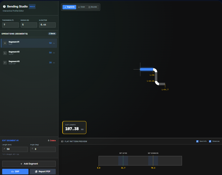
What it does
Experiment with K-factors, bend deductions, and neutral axis positions before sending programs to the press brake. Enter thickness, radius, and angles to see total flat length and per-bend allowances that align with ISO 2768 or ANSI style tolerance blocks.
When to use it (and when not to)
Use it when:
- You are drafting or revising press brake programs and want to validate allowances before production.
- You want to tune K-factor or bend deductions to match a new material batch or brake tooling.
- You need a quick training aid for apprentices learning how flange lengths change with different radii.
Avoid it when:
- You are modeling stamped, roll-formed, or highly non-linear bends that need FEA or vendor data.
- You need automatic flat patterns for complex multi-bend parts; run this per bend and combine the results.
Inputs and outputs
Inputs
| Input | Description |
|---|---|
| Material thickness | Gauge or thickness of the sheet you are bending. |
| Inside bend radius | Radius at the neutral axis region; drives allowance values. |
| Bend angle | Formed angle after springback; enter consistent units. |
| Flange lengths | Leg lengths adjacent to the bend that roll into the flat length. |
| K-factor or bend deduction | Choose to drive calculations with K-factor or a known deduction. |
| Material or tooling notes | Optional notes to remind you of die width, grain direction, or brake setup. |
Outputs
| Output | Format | Notes |
|---|---|---|
| Total flat length | Numeric | Length to program or cut before forming. |
| Bend allowance / deduction | Numeric | Computed from thickness, radius, and angle for the specified K-factor. |
| Neutral axis location | Numeric | Position expressed as a factor of thickness for reference. |
| Summary card | On-screen | Values to copy into CAM notes or travelers. |
How to use
- Enter sheet thickness and inside bend radius.
- Set the bend angle and flange lengths that need flattening.
- Choose whether to drive the math from a K-factor or a bend deduction.
- Review the resulting flat length and allowance numbers.
- Copy the values into your CAM program or save a screenshot for the router.
Example dataset: Thickness: 3 mm, Inside radius: 4 mm, Bend angle: 90 deg, Flanges: 50 mm and 75 mm, K-factor: 0.38.
- Expected output: Shows flat length and bend allowance for the two-leg bend so you can program the brake or CAM flat pattern.
Accuracy and verification
- Assumes air bending with a single K-factor across the bend.
- Does not account for grain direction or tooling wear; verify with a bent coupon before a full run.
- Keep your input units consistent; the tool does not convert mixed values.
- Use press brake test pieces to refine K-factor for each material lot.
FAQ
- Does it support multiple bends? Use it per bend or per leg; combine the results for complex parts.
- Can I work in inch and metric? Yes. Enter values in the units you use; the math is unit-agnostic.
- How do I export the numbers? Copy them directly from the summary or take a quick screenshot.
- Does it run offline? Yes. Everything runs locally in your browser.
- What if my brake uses bend deduction tables? Select bend deduction mode and plug in the table value to see the resulting flat length.
Related tools
Changelog
- Initial documentation.
Feedback / bug report
- Open a GitHub issue
- Email or DM with the slug
metal-bendingso we can reproduce the issue