Magnetic Level Gauge Configurator
Configure magnetic level gauge dimensions, connections, and options with a live sketch and PDF datasheet export.
Open utility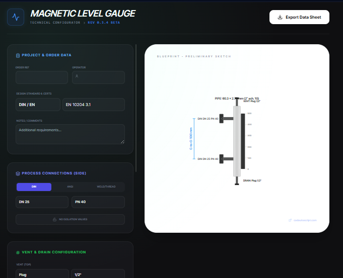
What it does
Select process connections, chamber dimensions, vent and drain options, and materials, then preview a live SVG sketch. Export a PDF datasheet that captures the selections for procurement or vendor review.
When to use it (and when not to)
Use it when:
- You are drafting a magnetic level gauge specification for a quote or internal review.
- You want to verify center-to-center dimensions and connection standards before ordering.
- You need a quick datasheet PDF to share with piping or instrumentation teams.
Avoid it when:
- You require certified pressure or float sizing calculations from a manufacturer.
- You are configuring guided wave radar or non-magnetic level instruments.
Inputs and outputs
Inputs
| Input | Description |
|---|---|
| Process connection standard and size | DIN, ANSI, weld, or threaded options for side connections. |
| Center-to-center dimension | Gauge chamber length used to scale the sketch. |
| Top and bottom connections | Vent and drain options such as plug, valve, or flange. |
| Materials and ratings | Chamber material, flange rating, and specific gravity assumptions. |
| Instrumentation options | Switches, remote transmitters, heating jackets, and indicator preferences. |
| Project metadata | Tag, line number, customer, and notes for the datasheet. |
Outputs
| Output | Format | Notes |
|---|---|---|
| PDF datasheet | Technical sheet with selections and a scaled sketch. | |
| Live SVG preview | SVG | On-screen sketch updating with your inputs. |
| Connection summary | On-screen | Process, vent, and drain callouts for review. |
How to use
- Choose the process connection standard, size, and rating.
- Enter center-to-center length plus vent and drain details.
- Set materials, specific gravity, and optional switches or transmitters.
- Add project metadata for traceability.
- Review the sketch and export the PDF datasheet.
Example dataset: Side connections: DIN DN25 PN40 RF, Center-to-center: 1800 mm, Top: 1/2 in NPT plug, Bottom: 1/2 in NPT valve, Material: 316L, Options: top and bottom sensors on, Heating jacket off, Tag: MLG-101.
- Expected output: Generates a PDF datasheet with the selected connections, dimensions, materials, and a live sketch for MLG-101.
Accuracy and verification
- Sketch dimensions are illustrative; confirm final dimensions with the vendor before fabrication.
- Pressure and temperature ratings must be validated against your design code.
- Specific gravity and float sizing are assumed; confirm with process data if critical.
- Files stay local until you download the PDF.
FAQ
- Can I switch between metric and imperial? Yes. Enter values in the units you use; the sketch scales accordingly.
- Is the PDF ready for submittal? It is a preliminary datasheet; obtain vendor confirmation for certified drawings.
- Does it store my tags? No. Close the page to clear entries or save the PDF for your records.
- Can I adjust vent and drain types? Yes. Pick plug, valve, or flange styles for top and bottom.
- Is any data sent to a server? No. Calculations and export run in the browser.
Related tools
Changelog
- Initial documentation.
Feedback / bug report
- Open a GitHub issue
- Email or DM with the slug
magnetic-level-gauge-configuratorso we can reproduce the issue