Dished End (Vessel Head) Calculator
Calculate geometry, blank diameter, and weight for Torispherical and Ellipsoidal heads (DIN 28011, DIN 28013, SS 895) with nozzle configuration, QC reports, and browser-based 3D STEP export.
Open utility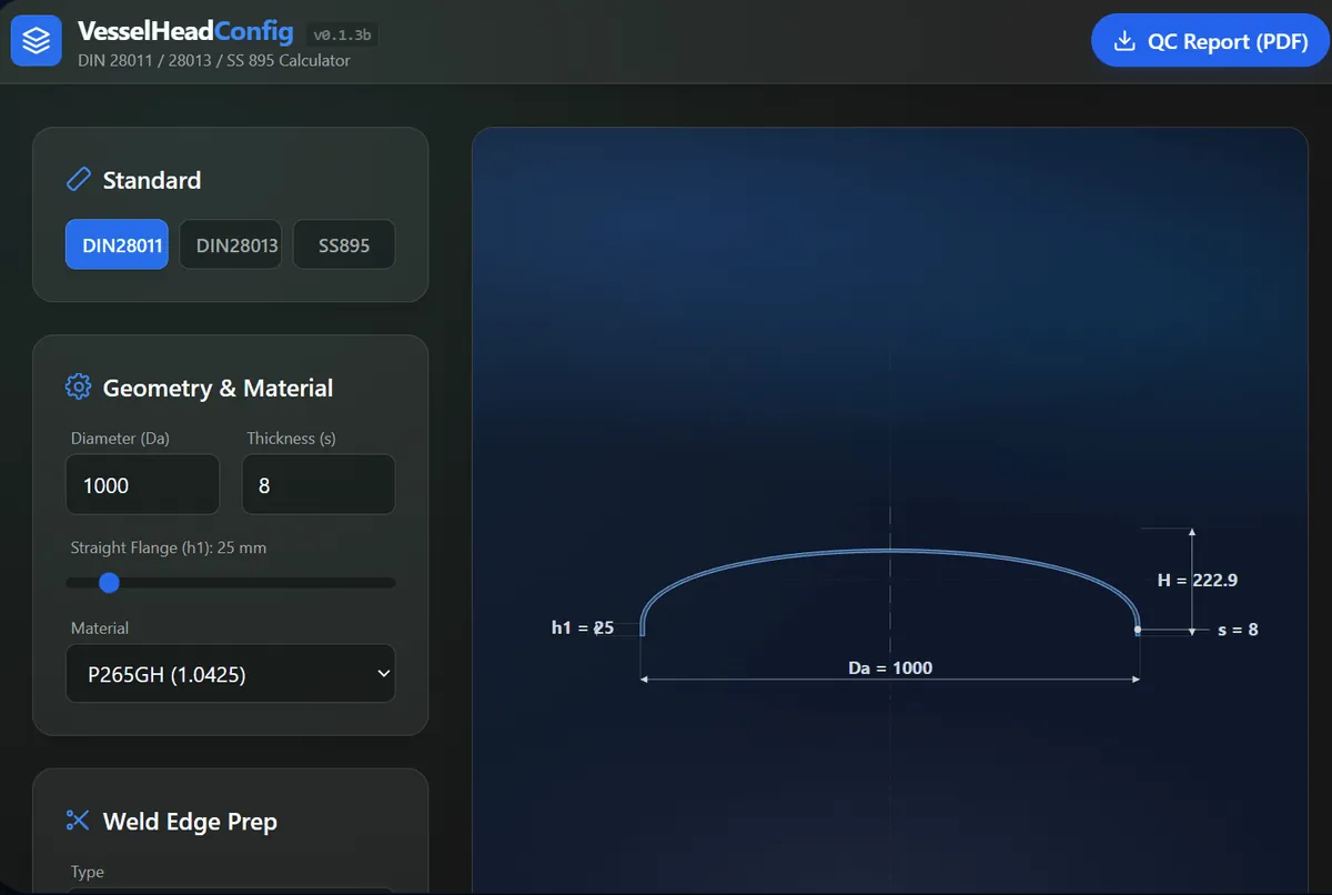
What it does
Instant calculation of pressure vessel head geometry, weight, and volume. It generates a visual profile including nozzle positions, exports a matching 3D STEP model, and produces a printable "Manufacturing Report" with expected tolerances for quality control.
When to use it (and when not to)
Use it when:
- You need to estimate the weight and blank diameter for material ordering.
- You want to visualize nozzle positions relative to the head curvature.
- You need a quick QC sheet with standard tolerances (DIN 28005-1) for the shop floor.
- You want a browser-side 3D STEP file of the configured head for downstream CAD work.
Avoid it when:
- You are designing ASME 2:1 Ellipsoidal heads (unless the geometry matches the provided DIN/SS presets manually).
- You require ASME VIII Div 1 pressure ratings or stress analysis.
Inputs and outputs
Inputs
| Input | Description |
|---|---|
| Standard | Choose between DIN 28011, DIN 28013, or SS 895. |
| Geometry (Da, s, h1) | Outer diameter, wall thickness, and straight flange height. |
| Material | Select from common grades (P265GH, Stainless, Titanium) to determine density. |
| Edge Prep | Configurable V-Bevel angle and root face dimensions. |
| Nozzles | Add nozzles with specific DN sizes and offset positions. |
Outputs
| Output | Format | Notes |
|---|---|---|
| Geometry (H, h2, R, r) | Numeric | Full height, crown height, dish radius, and knuckle radius calculations. |
| Weight & Volume | Numeric | Estimated finished weight and internal volume. |
| Blank Diameter | Numeric | Theoretical flat plate diameter required for forming. |
| 3D STEP model | STEP | Exports the configured vessel head geometry as a browser-generated 3D file. |
| QC Report | PDF/Print | A formatted sheet with nominal values and blank fields for actual measurements. |
How to use
- Select the manufacturing standard (e.g., DIN 28011).
- Enter the Outer Diameter (Da), Thickness (s), and Straight Flange (h1).
- Configure the material and edge preparation (bevel angle/root face) if needed.
- (Optional) Add nozzles by specifying size (e.g., DN50) and offset from center.
- Download the 3D STEP model when you need the current head as a CAD file.
- Click "QC Report (PDF)" to generate the printable manufacturing sheet.
Example dataset: Standard: DIN 28011, Da: 1000 mm, s: 8 mm, h1: 25 mm, Material: P265GH.
- Expected output: Total Height (H) calculated, weight estimation (~25kg), and a visual profile showing the dish radius and knuckle radius.
Accuracy and verification
- Geometry calculations follow the specific formulas for DIN 28011 (R=Da, r=0.1Da), DIN 28013, and SS 895.
- Tolerances in the report are derived from DIN 28005-1 (Formed Heads).
- Weight is calculated using standard densities (7.85 for Carbon Steel, 7.9 for Stainless).
FAQ
- Which standards are supported? DIN 28011 (Torispherical), DIN 28013 (Ellipsoidal), and SS 895.
- Does it calculate the blank diameter? Yes. It estimates blank diameter using standard factors (e.g., 1.09x or 1.14x Da) plus the straight flange.
- Can I configure weld preparation? Yes. You can select between a square cut (None) or a V-Bevel with configurable angle and root face.
- Is the QC report customizable? The QC report is auto-generated based on your inputs and includes DIN 28005-1 tolerances. It prints directly from the browser.
- Are my entries saved? No. Close the page to clear everything; it stays in your browser memory only.
Assumptions & standards
- Standards basis: Head geometry follows the relations of DIN 28011 (torispherical, R = Da, r = 0.1 Da), DIN 28013 (ellipsoidal), and SS 895; QC report tolerances are derived from DIN 28005-1 for formed heads.
- Key assumptions:
- Nominal dimensions per the selected standard, without forming tolerances applied to the calculated geometry.
- Uniform wall thickness across the head; thinning from forming is not modeled.
- Weight uses standard material densities (e.g., 7.85 kg/dm3 for carbon steel, 7.9 for stainless).
- Blank diameter is an estimate based on standard factors (e.g., 1.09x or 1.14x Da) plus the straight flange.
- Nozzle positions are treated as a visual layout guide, not a reinforcement calculation.
- Limitations:
- No pressure rating or stress analysis (e.g., ASME VIII Div 1 or EN 13445-3 design checks) is performed.
- Nozzle reinforcement, opening compensation, and weld design are not covered.
- ASME 2:1 ellipsoidal heads are not a native preset.
- Fatigue, corrosion beyond the entered allowance, and thermal effects are not considered.
- ⚠️ The Dished End (Vessel Head) Calculator provides preliminary sizing support. Results must be verified by a qualified engineer against the governing code edition and the project specification before manufacturing or purchase.
Why the knuckle governs a dished head
A torispherical head is three surfaces blended together: a spherical crown in the middle, a toroidal knuckle at the rim, and a short cylindrical straight flange that meets the shell. The standards define them as ratios of the diameter rather than free dimensions:
| Standard | Crown radius R | Knuckle radius r |
|---|---|---|
| DIN 28011 (Klöpper) | 1.0 × Da | 0.1 × Da |
| DIN 28013 (Korbbogen) | 0.8 × Da | 0.154 × Da |
The crown is the easy part — a sphere carries pressure in pure membrane tension and needs only about half the thickness of the cylinder it caps. The knuckle is where the trouble is: the curvature reverses there, so the material sees compressive hoop stress on top of the pressure load. Two consequences follow, and both show up in the calculator:
- Buckling, not bursting, is the usual failure mode of a thin knuckle. It wrinkles inward rather than splitting.
- Forming thins the knuckle most. The tool estimates about 12 % thinning there for a torispherical head and 14 % for the deeper ellipsoidal one — the largest reduction anywhere on the part, in exactly the region already carrying the least favourable stress.
That is why the blank module suggests a starting plate thicker than the nominal: you are ordering material so the knuckle still meets the specification after forming, not so the plate matches the drawing before it.
The Korbbogen head trades depth for a gentler knuckle — its larger r relieves
the stress concentration but costs a deeper draw and a larger blank
(1.14 × Da against 1.09 × Da), which is the trade shown side by side in the
validation cases below.
Validation cases
The calculation engine is guarded by an automated test suite; the cases below are taken directly from those tests, with the reference values computed by hand from the standard form factors. You can reproduce any of them in the calculator and compare digit for digit.
Case 1 — DIN 28011 torispherical (Klöpper) head
Inputs: outer diameter Da = 1000 mm, wall thickness s = 10 mm, straight
flange h1 = 40 mm, material carbon steel (ρ = 7.85 kg/dm³).
DIN 28011 form factors: crown radius R = Da, knuckle radius r = 0.1·Da,
dish depth h2 = 0.1935·Da − 0.455·s.
| Quantity | Hand calculation | Reference value | Tool output |
|---|---|---|---|
| Crown radius R | 1 × 1000 | 1000 mm | 1000 mm |
| Knuckle radius r | 0.1 × 1000 | 100 mm | 100 mm |
| Dish depth h2 | 0.1935·1000 − 0.455·10 | 188.95 mm | 188.95 mm |
| Total height | 40 + 188.95 + 10 | 238.95 mm | 238.95 mm |
| Blank diameter | 1.09·1000 + 2·40 | 1170 mm | 1170 mm |
| Blank weight | π·(585 mm)²·10 mm · 7.85 kg/dm³ | ≈ 84.4 kg | 84.4 kg |
Case 2 — DIN 28013 semi-ellipsoidal (Korbbogen) head
Same inputs, standard switched to DIN 28013 (R = 0.8·Da, r = 0.154·Da,
h2 = 0.255·Da − 0.635·s, blank factor 1.14).
| Quantity | Hand calculation | Reference value | Tool output |
|---|---|---|---|
| Crown radius R | 0.8 × 1000 | 800 mm | 800 mm |
| Knuckle radius r | 0.154 × 1000 | 154 mm | 154 mm |
| Dish depth h2 | 0.255·1000 − 0.635·10 | 248.65 mm | 248.65 mm |
| Blank diameter | 1.14·1000 + 2·40 | 1220 mm | 1220 mm |
Case 3 — forming thinning estimate (blank module)
For Case 1, the knuckle zone governs thinning at the engine's 12 % estimate
for torispherical forming: estimated minimum thickness
10 × (1 − 0.12) = 8.8 mm. Because the QC minimum is
10 − 0.3 = 9.7 mm, the tool raises a thinning warning and suggests a
starting plate of 10 / 0.88 = 11.36 → 11.5 mm (rounded up to the 0.5 mm
plate step) to end at nominal after forming.
These same numbers run as unit tests on every change to the calculation engine — a release that breaks any of them cannot be deployed.
Related tools
Changelog
- Added browser-based 3D STEP export for vessel heads.
- v0.1.3b: Added QC Report generation, nozzle configuration, and edge prep visualization.
- Initial release.
Feedback / bug report
- Open a GitHub issue
- Email or DM with the slug
pressure-vessel-dished-end-calcso we can reproduce the issue