Pipe Cutter Visualizer
Preview saddle intersections, adjust offsets, and export DXF wraps and hole templates for pipe fit-ups.
Open utility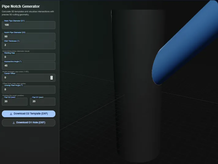
What it does
Pipe Cutter Visualizer renders pipe-to-pipe intersections in 3D so you can check the saddle fit before cutting. Enter run and branch diameters, tweak the intersection angle and offset, and download true-scale DXF wraps for the branch along with a matching cutout for the run pipe.
When to use it (and when not to)
Use it when:
- You know the run and branch diameters and need a wrap template for torch, plasma, or waterjet cutting.
- You want to preview clearance and offset before welding spool pieces.
- You need quick DXF geometry to drop into CAM or to print at 1:1 for the shop.
Avoid it when:
- You need reinforcement pad sizing or code calculations; this tool focuses on geometry only.
- The pipe is heavily ovalized or requires complex bevel allowances beyond simple offsets.
Inputs and outputs
Inputs
| Input | Description |
|---|---|
| Run pipe outside diameter (D1) | Base cylinder the saddle wraps around; note schedule or wall separately if needed. |
| Branch pipe outside diameter (D2) | Branch tube that will be notched and wrapped. |
| Intersection angle | Angle between run and branch centerlines; supports perpendicular or skewed joints. |
| Branch offset | Shift the saddle up or down to match real-world offsets before cutting. |
| Padding / trim allowance | Extra margin added to the DXF output so prints have bleed room for cutting. |
Outputs
| Output | Format | Notes |
|---|---|---|
| Branch wrap template | DXF | Unrolled saddle for wrapping the branch pipe at 1:1 scale. |
| Run-pipe cutout | DXF | Open polyline showing the hole to cut in the run pipe, with a reference box. |
| 3D preview | Viewport | Interactive view for checking alignment before exporting geometry. |
How to use
- Open the utility and enter diameters in the unit system you work with.
- Enter the run pipe OD, branch OD, and intersection angle.
- Add any offset or padding needed for your fit-up.
- Review the live 3D preview to confirm clearance and rotation.
- Export the DXF wrap and hole template, then print or send to CAM.
Example dataset: Run pipe OD: 114.3 mm, Branch OD: 60.3 mm, Angle: 45 deg, Offset: 10 mm, Padding: 5 mm.
- Expected output: Exports pipe_template.dxf and hole_template.dxf sized for a 1:1 print or CAM import.
Why a saddle cut is not a straight line
Push a round pipe against another round pipe and the line where they meet is a curve in three dimensions — the saddle. Wrap a sheet of paper around the branch pipe, trace that curve, unroll the paper, and the curve becomes a wave. That unrolled wave is the cut template.
The wave exists because the branch pipe meets the main pipe at different distances around its circumference. At the sides (the "crotch"), the branch has to reach further to touch the main pipe's curved surface; at the top and bottom of the saddle, less far. The template is the record of that varying reach, plotted against the distance travelled around the branch.
Three things set its shape:
- Diameter ratio. The closer the branch is to the main pipe's diameter, the deeper the saddle. A small branch on a large main pipe cuts almost flat; equal diameters produce the deepest, most sharply peaked curve.
- Axis angle. A 90° tee is symmetric. Tilt the branch and the curve becomes asymmetric — one side of the template stretches, the other compresses.
- Offset. Moving the branch off the main pipe's centreline shifts the whole intersection sideways, again breaking symmetry.
Set-on versus set-in — the choice that changes the template
This is the distinction most worth getting right, because the two produce different cuts from the same nominal dimensions.
Set-on — the branch sits on the outside of the main pipe. The cut follows the main pipe's outer surface, and the hole in the main pipe is only as large as the branch bore.
Set-in — the branch penetrates into the main pipe. The cut follows the main pipe's inner surface, so it is deeper, and the hole in the main pipe must clear the branch's full outer diameter.
The two templates are not a constant offset apart. For the worked example below the curves differ by up to 17.9 mm at their widest — far more than the 7.1 mm wall that separates the two surfaces, because the branch meets the main pipe at an angle and the penetration rule adds to it. Cutting a set-on template for a set-in joint therefore leaves a gap that varies around the circumference, which is why it cannot be corrected by grinding a little extra off one side.
Worked example — DN 150 main, DN 50 branch at 45°
A branch pipe 60.3 mm OD meeting a main pipe 168.3 mm OD at 45°, set-on, no offset.
Because the branch meets the main at an angle, the intersection is an ellipse rather than a circle: the branch's circular section is projected onto the main pipe's surface stretched by 1/sin 45° ≈ 1.41 along the axis direction.
The template's key dimension is the cut depth — the difference between the longest and shortest reach around the branch:
- At the crotch (the acute side, where the pipes form the tight angle) the branch reaches furthest and the cut is deepest.
- At the heel (the obtuse side) it is shallowest.
For this geometry the wave spans 60.3 mm of cut depth over the 189.4 mm circumference of the branch (π × 60.3). Wrapping the printed template around the pipe and cutting to the line reproduces that curve without any trigonometry at the saddle itself.
How much the angle matters is easiest to see by comparison — same two pipes, only the angle changed:
| Geometry | Cut depth |
|---|---|
| DN 50 branch on DN 150 main, 90° | 5.6 mm |
| the same branch at 45° | 60.3 mm |
| equal diameters (168.3 on 168.3) at 45° | 203.2 mm |
A right-angle tee on a much larger main pipe is nearly a flat cut. Tilt it to 45° and the depth grows more than tenfold — this is the case where cutting by eye stops working.
The check that catches most errors: the template's length must equal the branch circumference, π × OD = π × 60.3 = 189.4 mm. If the printed template does not measure that when wrapped, the print scaled — and every cut from it will be wrong by the same percentage.
Common pitfalls
- Printing "fit to page". The single most common failure. Always print at 100 % scale and verify against the printed ruler or the stated circumference before cutting.
- Using the branch ID instead of OD. The template wraps the outside of the branch, so it is sized on the outside diameter.
- Confusing set-on with set-in — see above; the error equals the main pipe's wall thickness and shows up as a gap at the crotch.
- Ignoring the weld gap. The template is the geometric intersection. If your procedure calls for a root opening, that allowance comes off the cut line.
- Forgetting the main pipe also needs a hole. For anything but the smallest branches the hole is not a circle — it is the same intersection curve seen from the other side, which is why the tool exports a separate main-hole template.
Accuracy and verification
- Assumes round pipes with negligible ovality; check against actual stock.
- DXF export is geometric only; add bevel gaps or weld preps in the shop program if needed.
- Print at 100% scaling and verify a quick paper wrap before committing to steel.
- Pressure or reinforcement checks must be done separately.
FAQ
- Can I work in inch and metric? Yes. Enter values in the units you use as long as you keep inputs consistent; the DXF follows your numbers.
- Are the DXF templates true scale? Yes. The exports are generated at 1:1. Disable any print scaling when plotting.
- Can I tweak bevel allowance or root gap? Use the padding or offset controls to leave extra material, then finish the bevel in CAM or at the bench.
- Does it run offline? Yes. The calculation and DXF export run in the browser and stay on your device.
- Which CAD tools open the DXF? Any DXF-capable tool (AutoCAD, Fusion, SheetCAM, etc.) can import the polylines.
Related tools
Changelog
- Initial documentation.
Feedback / bug report
- Open a GitHub issue
- Email or DM with the slug
pipe-cutterso we can reproduce the issue