Visual Gear Pair Calculator
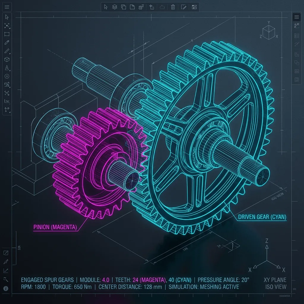
Calculate external cylindrical spur gear pair geometry, solve profile shifts and operating center distance, inspect the engaged tooth mesh in 2D and 3D, check forces and preliminary bending safety, and export manufacturing DXF files or 3D STEP CAD files—all locally in the browser.
Key Features
- Geometry Solver: Handles standard and profile-shifted ($x_1, x_2$) external spur gears. Computes operating pressure angle $\alpha_w$ and center distance $a_w$.
- Mesh Integrity Checks: Instant feedback on contact ratio, undercut warnings, gear-body/bore checks, and teeth interference.
- Ratio Search Engine: Suggests suitable combinations of tooth counts and modules to achieve a desired transmission ratio and center distance.
- Engaged 2D & 3D Previews: Dynamic previews with animation speeds matching input RPM, allowing visual inspection of mesh quality.
- CAD Exports: Export 2D closed polylines to DXF (with layers for profiles, pitch/base/outside/root circles) and 3D solids to STEP via a browser Web Worker (OpenCascade.js).
- PDF Calculation Reports: Generates print-ready documentation including formula derivations, warnings, assumptions, and dimension tables.
Supported Calculations
| Area | Parameters | Standards & Outputs |
|---|---|---|
| Geometry | Module, teeth count, pressure angle, shifts, backlash, face width | Pitch, base, outside, root diameters, operating center distance |
| Mesh Quality | Contact ratio, undercut bounds, overlap constraints | Transverse contact ratio ($\epsilon_\alpha$), profile integrity |
| Loads & Forces | Torque, speed (RPM), efficiency, service factor | Tangential force ($F_t$), radial ($F_r$), normal ($F_n$), pitch velocity ($v$) |
| Bending Safety | Allowable material stresses, service assumptions | Estimated bending stress ($\sigma_b$) and safety factor via Lewis check |
Important Notice
The calculations, stress estimates, and CAD files provided by this utility are for preliminary engineering reference, prototyping, and CAD mockups. Bending checks use a simplified Lewis formula and do not constitute a full ISO 6336 or AGMA rating. Always verify your final gear design against certified standards using specialized software before production release.
Basic Workflow
- Choose Sizing Mode: Select Existing Gear Pair Check to review specific dimensions, or Ratio-driven Sizing to search for candidates.
- Configure Sizing Inputs: Define basic gear parameters: module, pressure angle, tooth counts, face width, and profile shifts.
- Verify Warnings & Validation: Ensure the contact ratio badge is green ($> 1.4$) and that no undercut or interference errors are flagged.
- Inspect Visual Engagements: Check the 2D mesh sketch and 3D preview tabs. Toggle the animation to verify gear engagement direction.
- Download CAD and Reports: Export DXF files for cutting profiles, STEP files for CAD assemblies, and the PDF report for project records.
Assumptions & Standards
- Standards basis: Gear geometry follows the involute relations of ISO 21771-1 for external cylindrical spur gears; bending safety uses a simplified Lewis formula and is not a full ISO 6336 or AGMA rating.
- Key assumptions:
- External spur gear pairs only, with involute profiles and the entered pressure angle.
- Static or steady-state loading derived from the entered torque, speed, efficiency, and service factor.
- Uniform material properties and the allowable stresses you supply.
- Nominal dimensions without manufacturing tolerances or quality grades.
- Limitations:
- No surface durability (pitting), scuffing, or micropitting checks.
- Helical, internal, bevel, and worm gearing are not supported.
- Dynamic effects, load distribution factors, and lubrication analysis beyond the simplified force model are not covered.
- Results do not constitute a certified gear rating for production release.
- ⚠️ The Visual Gear Pair Calculator provides preliminary sizing support. Results must be verified by a qualified engineer against the governing code edition and the project specification before manufacturing or purchase.