Cylindrical Shell Rolling Calculator
Estimate roll spacing, bending allowance, and developed length for cylindrical shells with EN 13445 / ASME VIII presets.
Open utility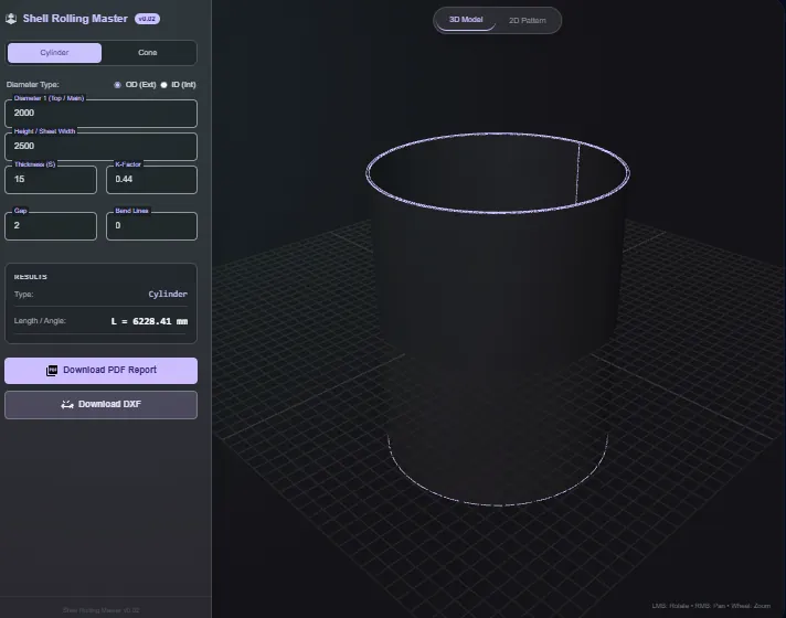
What it does
Calculate roll spacing, bending allowance, and developed length for cylindrical shells before the plate hits the rolls. Use EN 13445 or ASME VIII style presets, add seam gap or overbend allowances, and hand the spacing summary to the operator.
When to use it (and when not to)
Use it when:
- You need roll spacing and developed length for a cylindrical shell before releasing a job to the shop.
- You want to compare EN 13445 versus ASME VIII guidance or share offsets with an inspector.
- You want a printable setup card for operators without opening spreadsheets.
Avoid it when:
- You are rolling elbows, square-to-round transitions, or other shapes that are neither cylinders nor cones.
- You require finite element checks or machine capacity calculations beyond simple bending allowances.
Inputs and outputs
Inputs
| Input | Description |
|---|---|
| Target shell diameter | Outside or inside diameter the shell must hit after rolling. |
| Plate thickness | Material thickness that drives neutral axis and allowance. |
| Shell length and seam gap | Finished length plus any tack/fit-up gap you want to leave. |
| Standard preset | Choose EN 13445, ASME VIII, or custom allowances for your shop. |
| Overbend or flat-tail allowance | How much extra roll you want at the ends to minimize flat spots. |
| Roll spacing or machine geometry | Optional spacing inputs to sanity check capability and deflection. |
Outputs
| Output | Format | Notes |
|---|---|---|
| Roll spacing guidance | On-screen | Suggested spacing to hit the target diameter with minimal flat tails. |
| Developed flat length | Numeric | Length to cut the plate before rolling, accounting for seam gap. |
| Bending allowance / deduction | Numeric | Allowance values you can copy into your router or traveler. |
| Printable setup notes | Text | Copy or print directly from the page for the roll operator. |
How to use
- Enter the target shell diameter and finished length.
- Set plate thickness and pick the standard preset that matches your job.
- Add seam gap and any overbend or flat-tail adjustments.
- Review the roll spacing, developed length, and allowance numbers.
- Print or copy the values into the shop traveler.
Example dataset: Shell OD: 1500 mm, Thickness: 12 mm, Length: 2500 mm, Seam gap: 3 mm, Preset: EN 13445, Overbend: small end bias to reduce flat tails.
- Expected output: Outputs a developed length, roll spacing suggestions, and allowance values ready to share with the roll operator.
How the developed length is calculated
When a plate is rolled, its outer surface stretches and its inner surface compresses. Somewhere between them is a layer whose length does not change — the neutral axis. Cut the plate to that length and the finished shell comes out the right diameter; cut it to the outer or inner circumference and it will be wrong by several millimetres per pass.
The neutral axis does not sit exactly in the middle. Its position is expressed as the K-factor: the fraction of the wall thickness, measured from the inner surface, at which the material neither stretches nor compresses.
K = 0.5   neutral axis at mid-thickness (generous inner radius)
K = 0.44  typical for steel rolled to normal shell radii  ← default
K = 0.33  tight radii, where the inner fibre compresses more
The calculation is then two steps:
1. Convert the specified diameter to the neutral diameter. Which way depends on whether you entered an inside or an outside diameter:
from ID:   Dn = ID + 2·K·t
from OD:   Dn = OD − 2·t·(1 − K)
2. Take the circumference of that neutral diameter, minus the weld gap:
L = π·Dn − gap
The gap is the root opening you want left between the two plate edges before welding. Set it to zero for a closed butt.
Worked example — DN 2000 shell, 15 mm wall
A shell specified by outside diameter 2000 mm, wall 15 mm, height 2500 mm, rolled from steel (K = 0.44), with a 2 mm root gap.
Step 1 — neutral diameter. The OD is specified, so subtract the portion of the wall outside the neutral axis, from both sides:
Dn = 2000 − 2 × 15 × (1 − 0.44)
   = 2000 − 16.8
   = 1983.2 mm
Step 2 — developed length.
L = π × 1983.2 − 2
  = 6230.41 − 2
  = 6228.41 mm
So the blank is 6228 × 2500 mm. Cutting to the outer circumference instead (π × 2000 = 6283 mm) would have left the plate 55 mm too long — visible immediately as an overlapping seam.
What changes the answer most
| Change | Developed length | Difference |
|---|---|---|
| baseline (OD 2000, t 15, K 0.44, gap 2) | 6228.4 mm | — |
| K-factor 0.44 → 0.33 | 6218.0 mm | -10.4 mm |
| 2000 read as ID instead of OD | 6322.7 mm | +94.2 mm |
| wall 15 → 20 mm | 6210.8 mm | -17.6 mm |
| weld gap 2 → 4 mm | 6226.4 mm | −2.0 mm, exactly |
Confusing ID with OD dwarfs everything else — a +94 mm error, nearly ten times the effect of a wrong K-factor. It is the single most common reason a rolled shell will not close.
Validation cases
The calculation engine is guarded by an automated test suite (87 unit tests) that runs on every change and before every release. The cases below come directly from those tests, with reference values computed by hand from the closed-form relations above — not copied from the engine's output. You can reproduce them in the calculator and compare.
Case 1 — cylinder from OD and from ID
Inputs: diameter 2000 mm, wall t = 15 mm, K = 0.44, gap 2 mm, height 2500 mm.
| Specified as | Neutral diameter | Developed length |
|---|---|---|
| OD | 2000 − 2·15·0.56 = 1983.2 mm | π·1983.2 − 2 = 6228.41 mm |
| ID | 2000 + 2·0.44·15 = 2013.2 mm | π·2013.2 − 2 = 6322.65 mm |
The difference is 2πt = 94.25 mm for every K-factor: the two neutral
diameters differ by exactly one wall on each side, 2Kt + 2t(1 − K) = 2t. The
test checks this for K = 0.33, 0.44, 0.5 and 1.
Case 2 — K-factor and weld gap sensitivity
Same shell, specified by OD:
| Change | Expected | Why |
|---|---|---|
| K 0.44 → 0.33 | π·1979.9 − 2 = 6218.04 mm | ΔL = π·3.3 = 10.37 mm |
| K 0.3 → 0.5 | ΔL = 2π·15·0.2 = 18.85 mm | L grows linearly with K at 2πt per unit of K |
| K = 1 | neutral diameter = OD = 2000 mm | neutral axis on the outer surface |
| gap 2 → 4 mm | exactly 2.00 mm shorter | gap is subtracted one-for-one |
| gap 0 | π·1983.2 = 6230.41 mm | closed butt |
Case 3 — concentric cone
Inputs: OD 2000 → 1500 mm, height 2500 mm, t = 15 mm, K = 0.44, closed seam.
Neutral radii R_L = 991.6 mm, R_S = 741.6 mm.
slant height      s  = √(250² + 2500²)          = 2512.47 mm
outer radius      ρo = s·R_L / (R_L − R_S)       = 9965.46 mm
inner radius      ρi = ρo − s                    = 7452.99 mm
sector angle      θ  = 360·(R_L − R_S) / s       = 35.8213°
Checks: the outer arc ρo·θ equals the neutral circumference 2π·991.6, the
inner arc equals 2π·741.6, and swapping the wide and narrow ends gives the
same development. With a 6 mm gap the angle drops to 35.7819°: the gap is
removed as arc length on the neutral fibre, at the mean radius (ρo + ρi) / 2,
exactly as it is for a cylinder.
Case 4 — rejected input
The engine refuses rather than returning a misleading number:
| Input | Result |
|---|---|
| diameter, height or wall ≤ 0, NaN or infinite | rejected |
| K > 1, K ≤ 0 | rejected (K = 1 is accepted) |
| negative gap, or gap ≥ neutral circumference (6230.41 mm here) | rejected |
| wall ≥ neutral radius (e.g. OD 100, t 40, K 0.5) | rejected |
| cone with diameters less than 1 mm apart | rejected — use cylinder mode |
The eccentric-cone development is verified separately against independently known values: at zero offset it must reproduce the concentric sector above, its edges must keep the true circle lengths, and every ruling must lay out at its true 3D length.
Common pitfalls
- Rolling to the outer circumference. The most frequent error, and always in the same direction: the plate comes out too long and the seam overlaps.
- Using one K-factor for every job. It shifts with the radius-to-thickness ratio and with the material. For a first job on an unfamiliar alloy, roll a test coupon and back-calculate K from the result.
- Forgetting the gap is subtracted, not added. The gap is the opening left between the edges, so the blank is shorter, not longer.
- Springback is not in this number. The developed length is geometry. How much you overbend to land on the target diameter after release is a separate, machine- and material-dependent allowance.
Accuracy and verification
- Assumes a cylindrical shell with uniform thickness and moderate springback handled by the preset.
- Does not replace machine capacity checks or detailed stress calculations.
- Use mill test data to refine overbend for alloys that spring differently.
- Spot-check against a test coupon before running full-length plates.
FAQ
- Does it support inch as well as metric? Yes. Enter numbers in the unit system you use; calculations are unit-agnostic.
- Can I export the results? Use your browser print dialog or copy values into your own template; nothing is stored server-side.
- Does it calculate cones or elbows? It develops cylinders, concentric cones and eccentric cones. Elbows and other transitions are not supported.
- How is springback handled? Presets include typical tolerances. Adjust overbend or allowances for your material batch.
- Are my entries saved? No. Close the page to clear everything; it stays in your browser memory only.
Assumptions & standards
- Standards basis: Developed length and allowance values are based on standard plate-bending geometry relations, with tolerance presets styled after EN 13445 and ASME VIII fabrication guidance.
- Key assumptions:
- The shell is a cylinder, a concentric cone or an eccentric cone with uniform plate thickness.
- Springback is handled only through the preset tolerances and any overbend allowance you enter.
- Nominal input dimensions are used; plate thickness and diameter tolerances are not modeled.
- Material behavior is assumed typical for the preset; alloy-specific springback must be refined from mill test data.
- Limitations:
- Elbows, square-to-round transitions, and other non-conical shapes are not supported.
- No machine capacity, roll deflection, or finite element checks are performed.
- Weld shrinkage, ovality correction, and post-rolling heat treatment effects are not covered.
- ⚠️ The Cylindrical Shell Rolling Calculator provides preliminary sizing support. Results must be verified by a qualified engineer against the governing code edition and the project specification before manufacturing or purchase.
Related tools
Changelog
- Validation cases published; the engine is now covered by 87 unit tests that gate every release.
- Initial documentation.
Feedback / bug report
- Open a GitHub issue
- Email or DM with the slug
cylindrical-shell-rollingso we can reproduce the issue